We Design Billion-Euro Plants by Manually Copying Data
Process engineers design billion-euro plants, yet still copy data manually between drawings, spreadsheets, and simulations. This article explores how connected, machine-readable engineering models could reduce errors and improve decision-making.
Why process engineering needs a better way to manage technical data, changes, and dependencies
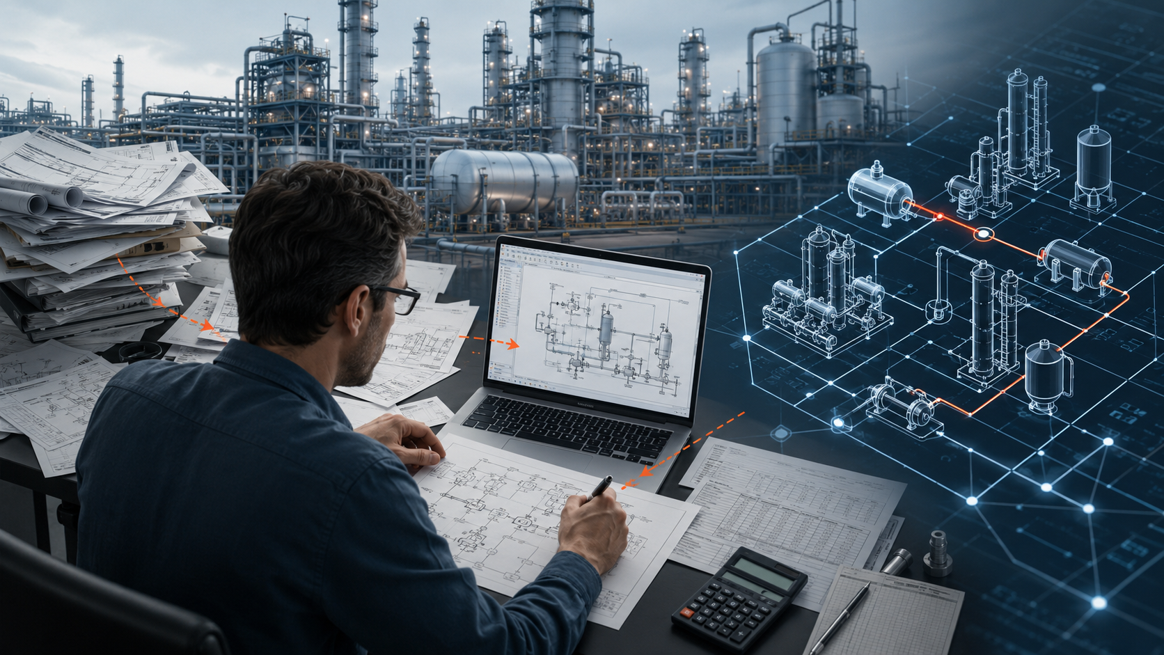
While working on a model of a cooling circuit for a chemical plant, I was given printed piping isometric drawings.
I needed to extract pipe lengths and diameters, elevation differences, valves, fittings, and other information required for the hydraulic calculations. I sat over the drawings, traced individual sections, and manually transferred the values into a process simulation and several calculation spreadsheets.
The data almost certainly already existed in digital form.
Someone had previously created a 3D piping model, generated the isometric drawings, checked them, and printed them. I then converted the same information from paper back into a form that another engineering tool could process.
Even at the time, this way of working felt rigid and outdated.
I had studied chemistry, thermodynamics, heat and mass transfer, and equipment design. Yet in that moment, I was acting primarily as a very expensive converter between a paper drawing and a process simulator.
The manual transcription itself was not what frustrated me most.
What frustrated me was that someone had already created the same information once. And that engineers on many other projects were probably repeating the same work again and again.
This was not an insignificant calculation. The result was supposed to be a model of a process circuit that could be used to assess pressure losses, flow rates, and the operating behaviour of the system.
We design plants that cost hundreds of millions of euros. Yet some of their important technical data are still transferred manually from drawings into spreadsheets and from spreadsheets into calculation software.
I do not think this is a problem unique to one project.
It is a symptom of a broader issue in how chemical and process engineering create, transfer, and update technical information.
An engineering design is an interconnected system
A process simulation, process flow diagrams, equipment specifications, piping calculations, and an economic evaluation are not independent documents.
They are different views of the same technology.
When the required production capacity changes, the consequences may propagate through:
- the material and energy balance,
- reactor size,
- the number of stages and diameter of a distillation column,
- reboiler and condenser duties,
- steam and cooling-water consumption,
- pipe diameters,
- pressure losses,
- pump sizing,
- capital expenditure,
- operating expenditure,
- and ultimately the economics of the process.
Imagine that the required plant capacity is increased by 15%.
The process simulator may recalculate the material and energy balance. But the work does not end there. Someone still has to determine whether the selected heat exchangers remain suitable, whether the reboiler duty has been exceeded, whether the piping diameters are still sufficient, and whether the pumps can deliver the required flow at the new pressure drop.
The change may be technically feasible but economically unattractive. It may preserve production capacity while reducing product purity. It may work at the design steady state while reducing the operating margin of key equipment.
An engineering design is therefore a network of interconnected assumptions, calculations, decisions, and constraints.
Our working tools, however, often divide it into isolated files.
Some information is stored in the process simulation. Some is in Excel. Some is in the PFD or P&ID. Other values are buried in equipment specifications, supplier documentation, meeting minutes, or email conversations.
Each of these documents may be correct on its own.
The problem appears when something changes.
Then someone has to identify every place affected by the change, update several calculations, transfer new values between programs, verify the dependencies, and hope that no document remains based on the previous design basis.
The larger the project, the more engineering disciplines, suppliers, documents, and software tools it contains. Keeping the entire design consistent becomes increasingly difficult.
We do not need another spreadsheet or another document.
We need a better way to preserve the relationships between the individual parts of the engineering design.
Many capable tools, but weak connections between them
Chemical and process engineering do not suffer from a lack of specialised software.
We have highly capable tools for:
- process simulation,
- hydraulic calculations,
- heat-exchanger design,
- computational fluid dynamics,
- mechanical and structural calculations,
- producing PFDs and P&IDs,
- 3D plant design,
- instrumentation and control,
- economic evaluation,
- and technical document management.
The quality of the individual tools is often not the main problem.
The problem exists between them.
Each program uses its own data structure. A stream in a process simulator, a pipe in a 3D model, and a row in a line list may refer to parts of the same physical system, but the tools may not understand how those objects relate to one another.
The connection is then maintained by a person.
A process engineer copies simulation results into a balance table. Values from that table are transferred into an equipment specification. A supplier returns a calculation in PDF format. The updated value is then entered manually into internal documentation and sometimes back into the simulation.
The engineer is not only assessing whether the design is technically sound.
The engineer is also acting as a manual converter of technical information between different tools.
This creates many opportunities for error:
- unit conversion mistakes,
- transcription errors,
- use of an outdated value,
- inconsistent naming of the same equipment,
- dependent documents not being updated,
- loss of information about the origin or justification of a change.
This way of working did not arise because process engineers or engineering companies do not understand technology.
It developed gradually.
As projects became more complex, more specialised tools, documents, checks, and formal requirements were added. Each of them addressed a legitimate need. The result can be a system that is technically robust but informationally fragmented.
What I mean by “Git for chemical engineering”
Git is a tool used in software development to record changes in detail.
It does not merely tell you that a document has reached “revision 3.” It can show precisely what changed between two versions, who made the change, and how the file developed over time.
For a process engineer, a similar principle could be understood as a detailed history of the technical model.
It would be possible to determine unambiguously that, for example:
- the design capacity increased from 100 to 115 kilotonnes per year,
- the reaction conversion changed from 92% to 94%,
- the distillation pressure decreased from 3 to 2 bar,
- the number of theoretical stages increased from 25 to 30,
- the maximum permitted steam consumption decreased from 2.5 to 2.2 MW.
This would be more than an archive of old files.
After each change, the system could rerun related calculations and show the technical consequences.
For example:
Increasing production capacity by 15% exceeded the design duty of the reboiler, increased cooling-water consumption by 18%, and reduced the available pump margin. The required product purity remained unchanged.
When I say that chemical engineering needs its own Git, I do not mean that process engineers should start working like software developers.
I mean that an engineering design needs a more precise history of changes, better traceability of decisions, and the ability to repeatedly verify their consequences.
A document revision tells us that the document changed.
We also need to know what changed in the technology.
A document written for a person is not enough for a machine
Technical documentation is essential.
We need it for communication, review, approval, procurement, construction, and operation. A drawing, table, or technical report can convey a large amount of information to an experienced engineer.
A computer, however, often does not understand its technical meaning.
A person can recognise that a value of 120°C represents the temperature of a stream entering a reactor. To a calculation program, it may be only a number in a particular spreadsheet cell or at a particular location in a drawing.
For technical information to be transferred and checked automatically, it must be clear:
- which stream or equipment item the value belongs to,
- which physical quantity it represents,
- which unit is used,
- where the value came from,
- and which other parts of the design depend on it.
A simple part of a process model could, for example, be written as follows:
process:
  name: formic-acid-production

streams:
  feed:
    temperature: 298.15 K
    pressure: 5 bar
    flow:
      methanol: 100 kmol/h
      carbon_monoxide: 105 kmol/h

units:
  reactor:
    type: conversion-reactor
    conversion: 0.92

  purification:
    type: distillation-column
    stages: 30
    pressure: 2 bar
This notation is called YAML. It is a simple text format that organises information into named groups.
A future solution does not necessarily have to use YAML. It could use a database, a specialised engineering format, or a combination of several representations.
The principle matters more than the format.
The value of 5 bar is not merely a number in a table. It is unambiguously defined as the pressure of a particular stream. The value 0.92 represents the conversion of a particular reactor. The value 30 identifies the number of theoretical stages in a particular column.
Such a structure can be read by both a person and a calculation program.
I use the working term Engineering as Code for this idea: an engineering design represented in a form that can not only be read, but also processed, compared, and checked automatically.
The first experiment does not need to describe an entire plant
Engineering as Code may sound like an excessively broad vision.
A complete plant design includes reaction and separation processes, equipment, piping, instrumentation and control, safety, civil engineering, electrical systems, economics, construction, and operational experience.
Attempting to unify everything in one system would probably be an excellent way to create a highly complex project without a practical result.
That is why I do not want to begin with a universal platform.
I want to start with one small and testable experiment:
Can a simple process be described in a structured file, automatically assembled in DWSIM, calculated, and evaluated without manual data transcription?
DWSIM is an open-source process simulator. It can work with chemical components, thermodynamic models, material streams, and common unit operations.
The first prototype could follow this sequence:
structured process description
              ↓
        input-data validation
              ↓
       model creation in DWSIM
              ↓
        simulation calculation
              ↓
     extraction of results and balances
              ↓
       verification of defined limits
The process engineer would define the components, thermodynamic model, feed streams, equipment, connections, and basic operating parameters.
The program would use this information to assemble the model, run the calculation, and return the results in a known structure.
Basic technical requirements could be defined together with the model:
checks:
  product_purity:
    value: product.mass_fraction.formic_acid
    requirement: ">= 0.85"

  reboiler_duty:
    value: purification.reboiler_duty
    requirement: "<= 2.5 MW"

  product_pressure:
    value: product.pressure
    requirement: "<= 3 bar"
After a change in capacity, pressure, or thermodynamic model, the calculation could be repeated. The system could then warn the engineer if:
- the required product purity was not achieved,
- the maximum reboiler duty was exceeded,
- a stream exceeded its permitted pressure,
- or the calculation no longer converged.
Such checks do not replace an experienced engineer, a safety analysis, or independent design verification.
They can only assess conditions that have been explicitly defined in advance.
They can, however, reveal quickly that a change in one part of the model has created an unexpected consequence elsewhere.
The first prototype should primarily answer practical questions:
- Which parts of a process simulation can be described unambiguously?
- How much information must be entered manually?
- Which data can be obtained from databases?
- How should physical units be handled?
- How difficult is it to extract results without manual copying?
- At what point does a structured description become impractical?
- Does this way of working create a real benefit for process engineers?
This is no longer a distant vision of a fully digital plant.
It is a specific technical experiment that can be built, demonstrated, and criticised.
Even the best model is not the real plant
Transferring some practices from software development into engineering has clear limits.
A physical plant cannot simply be restored to a previous version once it has been built. A poor design can lead to the loss of a major investment, a long shutdown, equipment damage, or risks to people and the environment.
A process simulation is also not the actual process.
It is a simplified mathematical representation based on assumptions and available data. Physical properties may not be known precisely. Feedstock quality changes. Equipment ages. Real operation deviates from the design point.
No shared data format can replace the experience of an engineer who recognises that a result may have converged mathematically while still making no physical sense.
Nor can a single model completely describe an entire technology.
A process simulation addresses a different part of the problem from CFD, mechanical calculations, control-system design, HAZOP, or economic evaluation.
Engineering as Code should therefore not become one enormous file containing everything.
It is more likely to become a set of connected engineering models with clearly defined inputs, outputs, and relationships.
The aim is not to replace the engineer.
The aim is to allow engineers to spend more time understanding the process, selecting the right technological concept, and assessing risks — and less time mechanically transferring the same values between documents.
Why I am working on this problem
During my career, I have worked on chemical process development, process simulation, separation processes, and the crystallisation of pharmaceutical substances.
At the same time, I have spent many years programming and building technical tools.
The combination of these two experiences led me to ask whether some problems that we accept as a normal part of engineering work are actually consequences of the way we handle technical information.
I do not claim to know the final solution.
YAML may be the wrong format. DWSIM may be too limited as a starting point. Existing industrial standards may already address important parts of the problem but remain underused.
Engineering as Code is not a finished product for me.
It is a hypothesis.
And the best way to test it is not another presentation or a long theoretical study. It is a small working model that makes both the benefits and the limitations visible.
I am looking for people who recognise this problem
I do not want to build a community of people who automatically agree with me.
I am interested in hearing from process engineers, technologists, industrial researchers, engineering and EPC companies, plant operators, and developers of specialised engineering software.
People who understand the reality of technical projects and can identify where this approach could help — and where it would fail.
The common goal does not need to be a single universal platform.
It may be based on a much simpler principle:
Engineers should spend their time understanding technology and making engineering decisions, not repeatedly transferring the same data between documents.
That leads me to one specific question:
Between which two tools or documents do you most often transfer technical data manually?
And if you believe that Engineering as Code would fail in a real industrial project, please explain exactly where.
The most valuable outcome may not be confirmation of the idea.
It may be discovering its boundaries.
Chemical engineering may not need Git in the literal sense.
But it certainly needs a better way to manage changes, preserve dependencies, and prevent technical information from being lost between the individual stages of a project.
And perhaps the best place to begin is with one small process model that does not have to be assembled manually every time.